2SA1301 Transistor Pinout, Equivalent, Applications, Features and More
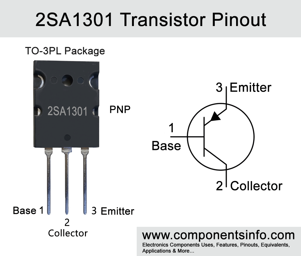
In this post we are going to discuss 2SA1301 transistor pinout, equivalent, applications, features, how to use this transistor and other details about this PNP power transistor.
Absolute Maximum Ratings:
- Package Type: TO-3PL
- Transistor Type: NPN
- Max Collector Current(IC): -12A
- Max Collector-Emitter Voltage (VCE): -160V
- Max Collector-Base Voltage (VCB): -160V
- Max Emitter-Base Voltage (VEBO): -5V
- Max Collector Dissipation (Pc): -120 Watt
- Max Transition Frequency (fT): -30 MHz
- Minimum & Maximum DC Current Gain (hFE): 35 To 160
- Max Storage & Operating temperature: -55 to +150 Centigrade
NPN Complementary:
NPN Complementary of 2SA1301 is 2SC3280
Replacement and Equivalent:
2SB1429, 2SA2151, 2SA2120, 2SA1962, 2SA1942, 2SA1492, 2SB1317
2SA1301 Transistor Explained / Description:
2SA1301 is a PNP transistor available in TO-3PL package. It is designed to be used in audio amplifier applications, but its versatile electrical characteristics makes it ideal for use in wide variety of applications. Looking at the features of the transistor, it has a high collector-emitter voltage, high power dissipation, transition frequency of 30MHz, and availability of NPN complimentary, etc.
The absolute maximum ratings of the transistor are: collector-emitter voltage of -160V, collector-base voltage of -160V, continuous collector current of -12A, continuous base current of -1.2A, collector power dissipation of 120W, junction temperature is 150°C and storage temperature is from -55°C to +150 °C.
2sa1301 is manufactured in two different gain values which can be determined with the help of the alphabet written after the part number. The Alphabet “R” means its gain value is 55-110, and alphabet “O” shows the gain value is 80-160.
How to Use this Transistor:
To use the transistor as a switch connect emitter pin with the positive rail of the circuit, apply signals to its base through a current limiting resistor. For current limiting resistor you can use any value from 1K to 10K. The lower resistor value will allow more current to flow from emitter to collector and the higher value allow less current flow. The collector pin will be connected with the load positive terminal and the negative terminal of the load will be connected with the negative rail of the circuit.
To use the transistor as an amplifier the emitter pin will be connected with the positive rail of the circuit, the signals which we want to amplify will be applied to the transistor’s base pin through a filter capacitor. An electrolytic capacitor from 1uf to 10uF can be used. The reason for using a capacitor here is to filter out only AC signals (audio signals are in AC form) and blocking DC voltage. The amplified output will be received at the collector pin of the transistor. This is just a basic procedure of using the transistor as an amplifier to make a fully working amplifier circuit you have to use some passive components also
Applications:
Audio amplifier stages
High power audio amplifiers
Motor Drivers Circuits
Drive load of up to 15A
Safe Operating Guidelines:
Here are some important points to safely operate the transistor:
- Always use it 20% below from its absolute maximum ratings.
- Check pin configuration before using in the circuit.
- Always use heatsink with the transistor.
- To not expose to temperatures above -55°C and below +150 °C.
Datasheet:
To download the datasheet just copy and paste the below link in your browser.
https://www.alldatasheet.com/datasheet-pdf/view/1088174/NJSEMI/2SA1301.html


