2SA1306/A/B Transistor Pinout, Equivalents, Features, Applications and Other Details
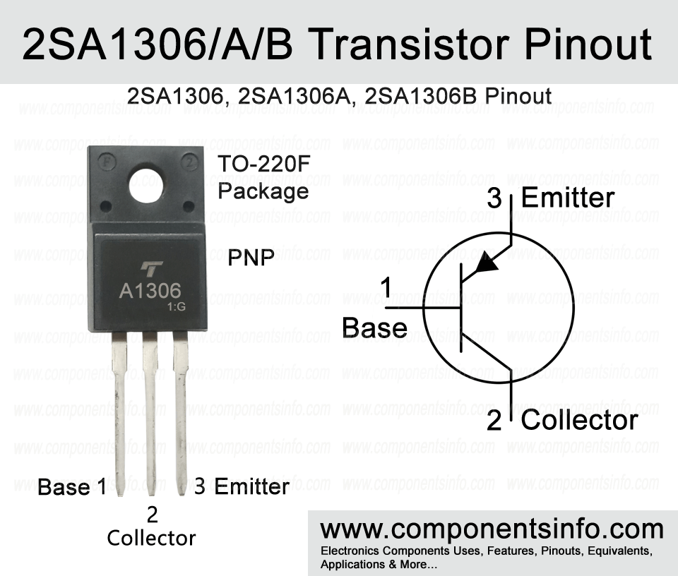
2SA1306 is a PNP transistor manufactured in TO-220F package. It has two more versions such as 2SA1306A and 2SA1306B which are slightly different in electrical characteristics. In this post we will understand its pinout, equivalents, features, applications and other details.
Absolute Maximum Ratings:
- Package Type: TO-220F
- Transistor Type: PNP
- Max Collector Current(IC): -1.5A
- Max Collector-Emitter Voltage (VCEO): -160V (2SA1306), -180V (2SA1306A), -200 (2SA1306B).
- Max Collector-Base Voltage (VCB): -160V (2SA1306), -180V (2SA1306A), -200 (2SA1306B).
- Max Emitter-Base Voltage (VEBO): -5V
- Collector Power Dissipation (PC): 20W
- Transition Frequency (fT): 100 MHz
- DC Current Gain (hFE): 70 to 240
- Max Storage & Operating temperature Should Be: -55 to +150 Centigrade
NPN Complementary:
NPN complimentary of 2SA1306/A/B is 2SC3298/A/B
Equivalents for 2SA1306:
2SB940, 2SA968, 2SA1306A, 2SA1306B, 2SB928, 2SA1500. You can also use the equivalents of 2SA1306A for 2SA1306.
Equivalents for 2SA1306A
2SA1306B, MJE5851, MJE5850, MJE15033, 2SB940A, 2SA968A/B. You can also use the equivalents of 2SA1306B for 2SA1306A.
Equivalents for 2SA1306B
MJE5852, MJE5851, MJE5850, MJE15033, 2SA1668, 2SA1668, 2SA1006/A/B
2SA1306/A/B Transistor Explained / Description:
2SA1306 or A1306 is a PNP transistor designed to be used in audio amplifier applications. The transistor also has two other versions such as 2SA1306A and 2SA1306B which are slightly different in their collector-emitter, collector-base ratings.
Understanding the absolute maximum ratings of these transistors: As mentioned above the only different between these three versions are their collector-emitter and collector-base voltages & all other ratings are same. So the collector-emitter and collector-base of 2SA1306 is -160V, 2SA1306A is -180V and 2SA1306B is -200V. The other ratings of all the three versions are same, such as a continuous collector current of -1.5A, emitter-base voltage of -5V, continuous base current of -0.15A, collector power dissipation of 20W, junction temperature of 150°C and storage temperature is from -55°C to +150°C.
According to their DC current gain each transistor of all three versions is available in two different gain variations and can be identified by the alphabet written after their part number. So if that alphabet is “O” then its gain will be 70-140 and if it is “Y” then its gain will be 120-240.
As mentioned above these transistors are designed to be used in audio amplifier applications but if you have it in your spare then you can also use it other many other applications such as RF and switching applications.
How to Use this Transistor:
Using transistor as a switch is easy as compare to using it as an amplifier because wiring it as a switch is pretty straight forward, but to wire it as an amplifier requires to use some passive components to get the desired results. In this how to guide we will discuss only the basic procedure so you can understand the concept.
To use the transistor as a switch connect its emitter pin with the positive rail of the circuit, apply the signals at the base of the transisor (the signals from which you want to control the output load). A resistor of 1K to 10K can be used depends how much output current you require. The load will be derived with the collector of the transistor. The positive pin of the load will be connected with the collector and the negative pin will be connected to the ground or negative rail of the power supply.
To use the transistor as an amplifier, connect its emitter with the positive rail of the power supply. Apply signals which you want to amplify to the base through an electrolytic capacitor. The reason for using an electrolytic capacitor in series here is because it is a good device for blocking the DC current and only allows the AC signals (since audio signals are in AC form in audio amplifiers) to transfer through it. The amplified signals will be available at the collector of the transistor. Here you can connect an audio device such as a speaker or you can also fed this output to another amplifier or stage.
Applications:
Audio Amplifier Circuits
Audio Amplifier Stages
Switching Circuits
Radio Frequency Circuits
Darlington Pairs
Other General Purpose Applications
Safe Operating Guidelines:
Safe operating guidelines for the transistor.
- Always use the transistor at least 20% below from its absolute maximum ratings.
- Check pin layout before using in the circuit.
- The storage and operating temperature limits are from -55°C to 150°C.
Datasheet:
To download the datasheet just copy and paste the below link in your browser.
https://www.alldatasheet.com/datasheet-pdf/view/1088179/NJSEMI/2SA1306.html


