2SA999 Transistor Pinout, Equivalent, Applications, Features, How to Use It and More
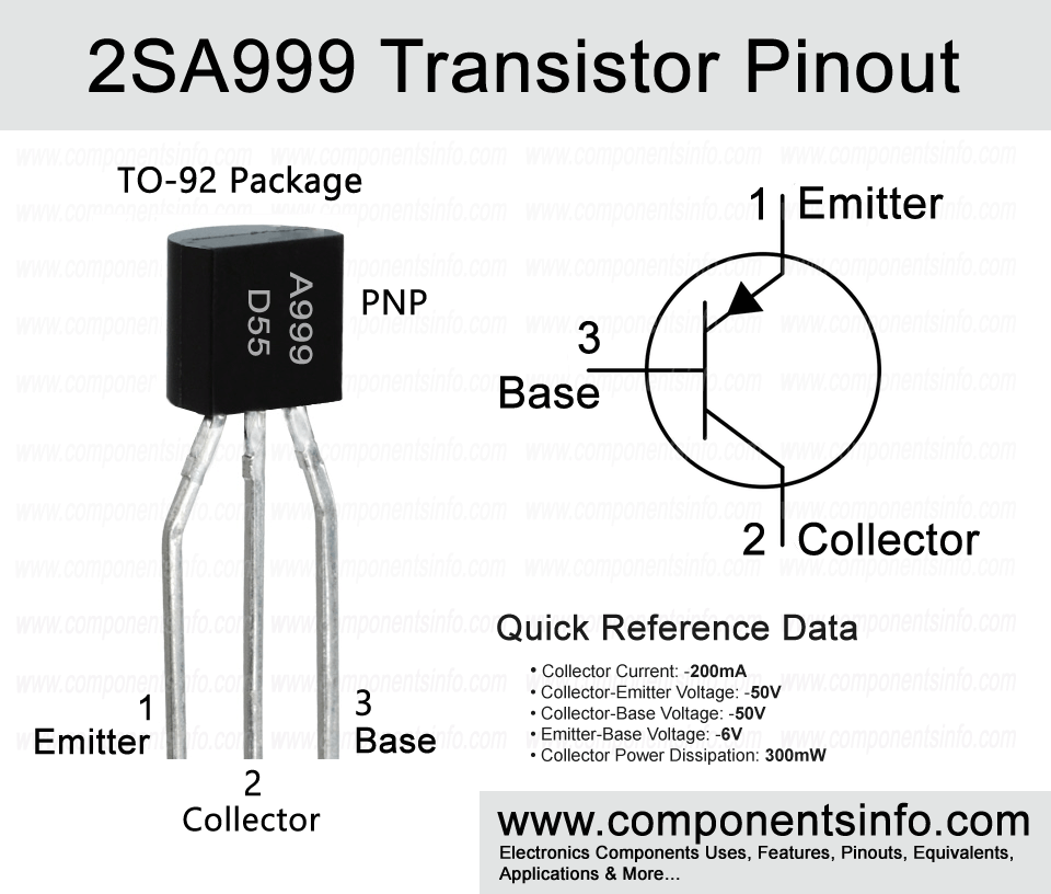
In this post we are going to discuss 2SA999 transistor pinout, equivalent, applications, features, how to use it and more.
Absolute Maximum Ratings:
- Package Type: TO-92
- Transistor Type: NPN
- Max Collector Current(IC): –200mA
- Max Collector-Emitter Voltage (VCE): –50V
- Max Collector-Base Voltage (VCB): –50V
- Max Emitter-Base Voltage (VEBO): –6V
- Collector Power Dissipation (Pc): 300mW
- Transition Frequency (fT): 200 MHz
- DC Current Gain (hFE): 90 to 800 (Four different variations, See text.)
- Max Storage & Operating temperature Should Be: -55 to +150 Centigrade
NPN Complementary:
NPN complimentary of 2SA999 is 2SC2320.
Replacement and Equivalent:
2SA1392, 2SB1312, 2SA1391
2SA999 Transistor Explained / Description:
2SA999 is a PNP transistor available in TO-92 package. It is designed to be used in audio amplifiers and low noise audio applications.
The transistor has many features such as transition frequency of 200MHz, DC current gain of 90 to 800 and max noise figure of 2dB. These features and its characteristics make it suitable to use in wide variety of applications.
The transistor is available in four different hFE variations that can be determined by the last the alphabet written on the transistor. If that alphabet is “D” then the transistor’s hFE will be 90 to 180, if “E” then 150 to 300, if “F” then 250 to 500 and if “G” then its DC current gain will be 400 to 800.
Looking at the absolute maximum ratings of the transistors the collector current of the transistor is -200mA, collector-emitter voltage is -50V, collector-base voltage is -50V, emitter-base voltage is -6V, collector power dissipation is 300MHz and storage and operating temperature is between -55°C to 150°C.
How to Use this Transistor:
Here is the procedure to use the transistor as a simple switch or amplifier.
To use it as a switch connect emitter pin with the positive rail of the circuit, apply signal to the base pin through a suitable current limiting resistor and connect the load between collector and negative rail of the circuit.
To use it as an amplifier connect the emitter pin with the positive rail of the circuit, apply audio signals which you want to amplify to the base pin of the transistor through an electrolytic capacitor. Usually a 1uF to 10uF capacitor is used. And connect the sound device such as speaker between the collector and negative rail of the circuit. Again an electrolytic capacitor of the same value that you have used at the input will also be used at the output between collector and the load.
Applications:
Signal Amplification
Switching Circuits
Audio Amplifier Circuits
Audio Preamplifier Circuits
Tx and Rx Circuits
Darlington Pairs
Audio Amplifier Stages
Safe Operating Guidelines:
Follow these guidelines to safely operate the transistor:
- Do not operate the transistor to its absolute maximum ratings and stay at least 20% below from these ratings.
- The maximum collector current is -200mA but according to the above 20% below usage guidelines do not drive load of more than 160mA.
- The maximum collector-emitter voltage is -50V so do not drive load of more than -40V.
- Check pin layout always before use.
- Do not store or operate temperature above -55°C to 150°C.
Datasheet:
To download the datasheet just copy and paste the below link in your browser.
https://www.alldatasheet.com/datasheet-pdf/view/107734/ETC/2SA999.html


