2SC5171 Transistor Pinout, Equivalents, Applications, Features and Other Related Info
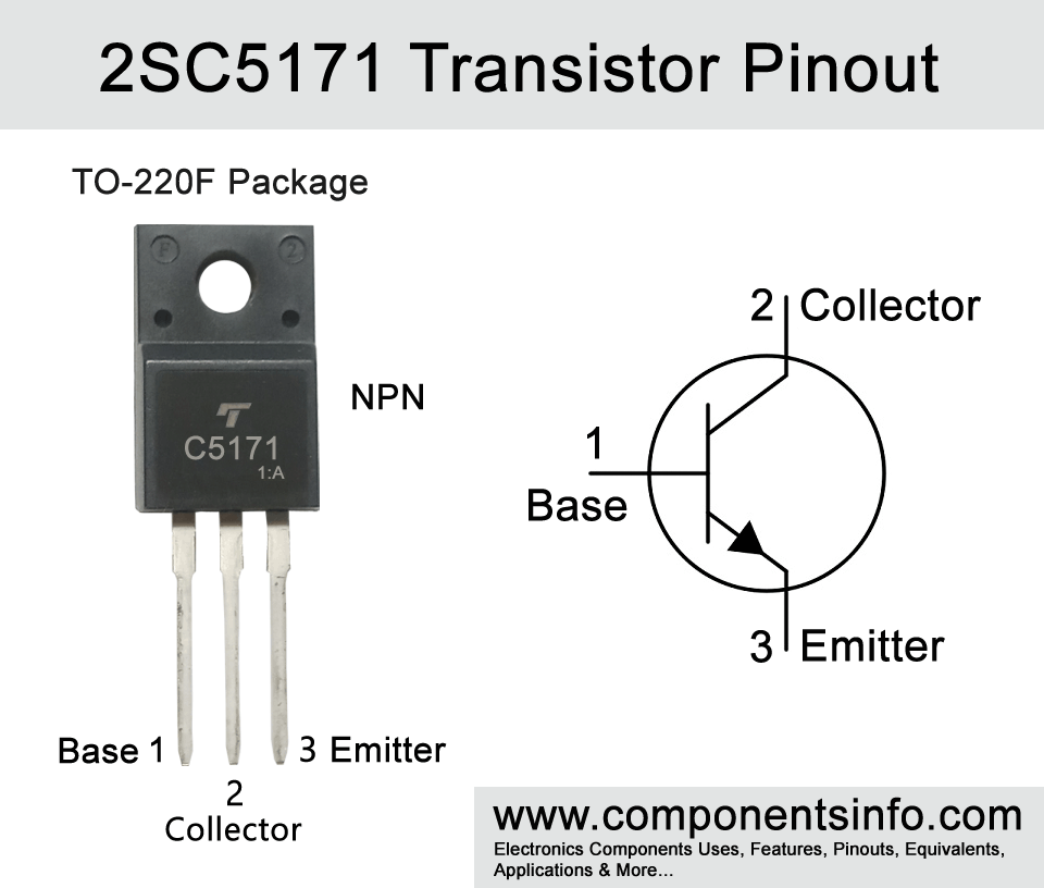
2SC5171 is an NPN transistor available in TO-220F package. It is designed to be used in amplifier applications. This article is all about 2sc5171 transistor pinout, equivalents, applications, features and other related information.
Absolute Maximum Ratings:
- Package Type: TO-220F
- Transistor Type: NPN
- Max Collector Current(IC): 2A
- Max Collector-Emitter Voltage (VCE): 180V
- Max Collector-Base Voltage (VCB): 180V
- Max Emitter-Base Voltage (VEBO): 5V
- Collector Power Dissipation (Pc): 20W
- Transition Frequency (fT): 200 MHz
- DC Current Gain (hFE): 100 to 320
- Max Storage & Operating temperature Should Be: -55 to +150 Centigrade
PNP Complementary:
PNP complimentary of 2SC5172 is 2SA1930
Replacement and Equivalent:
2SC517, 2SC1861, 2N5154, MJE15034, MJE15032, 2SD792A
2SC5171 Transistor Explained / Description:
2SC5171 is a high voltage NPN transistor designed to be used in driver stages of amplifiers and in power amplifiers. The transistor has some good features such as high collector-emitter voltage of upto 180V, transition frequency of 200MHz, DC current gain of 100 to 320 and collector dissipation of 20W. All these features make this transistor a good device to be used in variety of audio related applications.
The absolute maximum ratings of the transistor are collector-emitter voltage of 180V, collector-base voltage is also 180V, collector current is 2A, emitter-base voltage is 5V and collector power dissipations upto 20W.
The transistor is designed for to be used in audio related applications such as audio driver stages, audio amplifiers but it is not limited to these applications and can also be used in variety of other applications some of which are RF circuits, power circuits, controlling circuits, switching, high voltage etc.
How to Use this Transistor:
The using procedure of the transistor is same as we use other NPN BJT transistors. Here I am describing the two simple methods to use the transistor as a switch and amplifier.
To use it as a switch the emitter pin will be connected with the ground, signal will be applied at the base pin through a suitable current limiting resistor and the load will be connected between the collector and the positive rail of the circuit.
Now to use it as a simple amplifier the emitter pin will be connected with the ground, signal will applied to the base pin through an electrolytic capacitor of any value between 1uF to 10uF and the output device such as speaker will be connected between collector and the positive rail of the circuit. The same value electrolytic capacitor should also be used between and collector and speaker connection.
Applications:
Audio Amplifier Circuits
Signal Amplification
Audio Preamplifier Circuits
Audio Amplifier Stages
Switching Circuits
Radio Frequency Circuits
Tx and Rx Circuits
Darlington Pairs
Safe Operating Guidelines:
Safe operating guidelines for the transistor.
- Do not use the transistor to its absolute maximum ratings and stay at least 20% below from the absolute maximum ratings.
- So the maximum collector-emitter voltage is 180V but according to these guidelines we only use 80% which will be 144V.
- The maximum collector current is 2A but according to the above 20% below usage guidelines we will only use 1.6A.
- Operating and junction temperature of the transistor is from -55°C to 150°C.
Datasheet:
To download the datasheet just copy and paste the below link in your browser.
https://www.mouser.com/datasheet/2/408/7870-24209.pdf


