BDW84C Transistor Pinout, Equivalent, Applications, Features and More
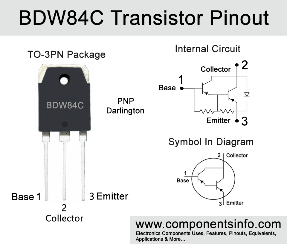
BDW84C is a PNP Darlington transistor available in TO-3PN and TO-218 packages. This post explains BDW84C transistor pinout, equivalent, applications, features and other details such as where and how to use it, etc.
Absolute Maximum Ratings:
- Package Type: TO-3PN & TO-218
- Transistor Type: NPN Darlington
- Max Collector Current(IC): -15A
- Max Collector-Emitter Voltage (VCEO): -100V
- Max Collector-Base Voltage (VCBO): -100V
- Max Emitter-Base Voltage (VEBO): -5V
- Max Continuous Base Current: -0.5A
- Max Collector Power Dissipation (Pc): 150 Watt
- Minimum DC Current Gain (hFE): 750 to 20000
- Max Storage & Operating temperature: -65 to +150 Centigrade
NPN Complementary:
NPN Complementary of BDX84C is BDW83C
Replacement and Equivalent:
BDW84D, TIP36CA, MJH6287, BDV66D
Low voltage equivalents are: BDW84, BDW84A, BDW84B
BDW84C Transistor Explained / Description:
Previously we have discussed BDW83C transistor now here is its complimentary BDW84C, both of these are used together in many types of audio amplifiers as complementary pairs. BDW84C is a PNP Darlington transistor available in TO-3PN and TO-218 packages. Like BDW83C, BDW84C has also a series in which there is BDW84, BDW84A, BDW84B, and BDW84D. The BDW84D can be used as a replacement for BDW84C in almost any application. The other transistors of the series can also be used as an alternative only in condition if your load requires a low voltage. Therefore you can select your transistor as an alternative according to your load requirements. You can check their collector-emitter voltage to select them according to your load requirements, but one thing should be kept in mind: always select transistors with collector ratings 15V to 20V higher than the load requirements.
Looking at the absolute maximum ratings of the transistor the collector-emitter voltage is -100V, the continuous collector current is -15A, emitter-base voltage is -5V, continuous base current is -0.5A, and the collector power dissipation is 150W.
The transistor has quite good gain capability which is from 750 to 20000 which makes it an ideal candidate to be used for audio amplification purposes but it can also be used to for switching and other general purpose applications which are mentioned under the “Applications” heading below.
Where We Can Use it & How to Use:
The transistor is designed to be used in general purpose switching and amplification purposes but it is not limited to these applications and can also be used in variety of other applications such as driver circuits, voltage converter circuits, pulse generation circuits, and others.
To use the transistor as a switch first check the pinout of the transistor and then connect the Base pin of the transistor to the signal source from which you want to control the load. A suitable resistor should be used between the Base pin and the signal source to limit the current that goes in the transistor, usually, any resistor with a value between 1K to 5K ohms can be used. Then connect the Emitter pin with the positive supply of the circuit and the Collector pin with the positive connection of the load and the negative connection of the load will be connected with the negative supply of the circuit.
Now to use the transistor as a simple amplifier connect the Base pin (through a 102 ceramic capacitor or you can also use a suitable electrolytic capacitor) with the signal source you want to amplify. Connect the Emitter pin with the positive supply of the circuit and connect the Collector pin with the positive connection of the speaker and the negative pin of the speaker will be connected with the negative supply or ground of the circuit. Please note that this is a very basic audio amplifier circuit and you can enhance it according to your need by adding some passive components.
Applications:
Motor Control
Audio power amplifier
Switching regulator
Inverter Circuits
Voltage Regulation
Relay Drivers
Voltage inverters
LED Drivers
Driver circuits
DC to DC Converter
Pulse Generator
Battery Operated Applications
Safe Operating Guidelines:
Here are the operating guidelines of the transistor.
- Do not drive the transistor to its absolute maximum ratings and always stay 20% below from these ratings.
- The maximum continuous collector current of the transistor is -15A so according to the 20% rule above do not drive load of more than -12A.
- Same applies to the load voltage, the maximum collector-emitter voltage is -100V so we will drive load of under -80V.
- And the temperature should be maintained between -65°C to 150°C.
Datasheet:
To download the datasheet just copy and paste the below link in your browser.
https://datasheetspdf.com/pdf-down/B/D/W/BDW84C-INCHANGE.pdf


