BC214 Transistor Pinout, Equivalents, Applications, Features and Other Details
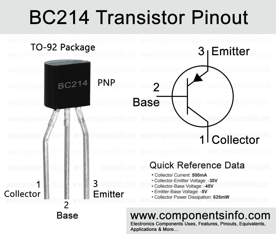
BC214 is a PNP bipolar junction transistor designed to be used in general purpose applications. The transistor is manufactured by different manufacturers and each manufacturer has made it in slightly different specs so it is important to check each manufacturer datasheet before purchasing. In this post we are going to discuss BC214 transistor pinout, equivalents, applications, features and other details about this device.
Absolute Maximum Ratings:
- Package Type: TO-92
- Transistor Type: PNP
- Max Collector Current(IC): –500mA
- Max Collector-Emitter Voltage (VCE): –30V
- Max Collector-Base Voltage (VCB): –45V
- Max Emitter-Base Voltage (VEBO): –5V
- Total Device Dissipation (Pc): 625 miliWatt
- Max Transition Frequency (fT): 200 MHz (Minimum)
- Minimum & Maximum DC Current Gain (hFE): 100 to 400
- Max Storage & Operating temperature Should Be: -55 to +150 Centigrade
Replacement and Equivalent:
BC526C, BC526B, BC214C, BC214B, 2SB1059, 2SA1625, 2SA1392, 2SA1391, 2SA1318
BC214 Transistor Explained / Description:
BC214 is a general purpose transistor designed to be used in general purpose applications but according to its specs it can also be used in general purpose switching and variety of other applications. The transistor has many good features which makes this transistor quite interesting such as continuous collector current of -500mA, DC current gain of 100 to 400, max noise figure of 2.0dB, transition frequency of 200MHz and total device dissipation of 625mW.
Now looking at the absolute maximum rating of the transistor the collector-emitter voltage is -30V, collector-base voltage of -45V, emitter-base voltage is -5.0V, collector current (continuous) is -500mA and max operating and storage junction temperature is from -55°C to +150.
All the above features and characteristics make this transistor ideal to be used in wide variety of applications such as low noise high gain applications, RF applications, switching applications, etc.
How to Use This Transistor:
Here is a simple straightforward procedure to understand the basic concept of how to use this transistor. To use as a switching the emitter of the transistor will be connected with the positive rail of the circuit. Signals from which you want to control the output load will be applied to the base of the transistor through a suitable current limiting resistor, and load will be connected between the collector and negative rail of the circuit.
Now to use it as an amplifier the procedure will be almost same but an amplifier circuit requires more passive components to enhance the audio output. Connect the emitter with the positive rail of the circuit, apply signal which you want to amplify at the base pin through a capacitor and the sound device such as a speaker will be connected with the collector through a capacitor and the negative pin of the speaker will be connected with the negative rail of the circuit.
Applications:
Audio Preamplifier Circuits
Tx and Rx Circuits
Switching Circuits
Darlington Pairs
Audio Amplifier Circuits
Audio Amplifier Stages
Solar Circuits
Battery Charger Circuits
Low Level Signal Amplification
Automotive Circuits
Safe Operating Guidelines:
Here are some guidelines for safe operation of the transistor.
- Do not operate the transistor to its absolute maximum ratings and always stay 20% below from its absolute maximum ratings.
- The max collector-emitter voltage is -30V so according to the above 20% guidelines do not drive load of more than -24V.
- The max continuous collector current is -500mA so do not use load of more than -400mA.
- The maximum storage and operating temperature limits are -55°C to 150°C.
Datasheet:
To download the datasheet just copy and paste the below link in your browser.
https://www.alldatasheet.com/datasheet-pdf/view/179517/FAIRCHILD/BC214.html


