TIP141 Transistor Pinout, Features, Equivalents, Applications and More
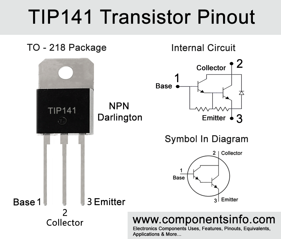
TIP141 is a TO-218 package dalington transistor designed to be used in general purpose applications. In this article we are going to discuss TIP141 transistor pinout, features, equivalents, applications and more.
Absolute Maximum Ratings:
- Package Type: TO-218 Or SOT-93
- Transistor Type: NPN Darlington
- Max Collector Current(IC): 10A
- Max Collector-Emitter Voltage (VCE): 80V
- Max Collector-Base Voltage (VCB): 80V
- Max Emitter-Base Voltage (VEBO): 5V
- Max Collector Dissipation (Pc): 125 Watt
- Minimum & Maximum DC Current Gain (hFE): 500 To 1000
- Max Storage & Operating temperature: -65 to +150 Centigrade
Complimentary PNP Transistor:
The Complimentary PNP transistor for TIP141 is TIP146
Replacement and Equivalent:
BDV65B, BDV65C
TIP141 Transistor Explained / Description:
TIP141 is a transistor of TIP14X series of darlington transistors available in TO-218 package. These transistors possesses some good features which are high collector-emitter voltage of 80V, max collector current of 10A, max peak collector current of 15A, max collector dissipation of 125 Watts, DC current gain of 500 to 1000 and availability of their complimentary transistors.
The pin layout of TIP141 are as follows: when looking from the from (part number side) the first pin is base, second pin is collector in the middle and the third pin is emitter.
Looking at the absolute maximum ratings of the transistor collector current is 10A, collector-emitter voltage is 80V, emitter-base voltage is 5V, collector-base voltage is 80V, collector dissipation is 125 Watt and storage and operating temperature range is -65°C to +150 °C.
The transistor is designed to be used in general purpose applications such as amplifier and as a switch in low frequency applications. The detailed list of its applications can be found applications heading below.
How to Use the Transistor:
Here I am going to explain simple procedures to use the transistor so you can understand the basic concept of using the transistor.
To use it as a switch connect its emitter pin with the negative rail of the circuit, apply signals through which you want to control the output load at the base pin through a suitable base resistor (it is an NPN transistor so the signal you are providing at the base pin will be positive). The load will be connected between the collector and positive rail of the circuit. The positive wire of the load is connected with the positive rail of the circuit and the negative wire of the load will be connected with the collector pin of the transistor. One thing should be kept in mind that if you are using current sensitive devices as a load such as LEDs, transistors, ICs etc then you have to use a current limiting resistor between collector pin and the load.
To use the transistor as a simple amplifier connect its emitter pin with the negative rail of the circuit, apply signals you want to amplify at the base pin through a capacitor (an electrolytic capacitor will work well). You can usually use a capacitor between 0.47uF to 10uF. Connect the sound device such as a speaker between collector and the positive rail of the circuit and use a same value electrolytic capacitor between the speaker and the collector pin of the transistor. The usage of the capacitor at the input and output is important because it has many benefits, its blocks DC, do signal coupling and also manages frequency responses.
Applications:
Motor Drivers
Audio amplifiers
Drive load of up to 10A
And many other general purpose applications
Safe Operating Guidelines:
To use the safely here are some safety guidelines:
To safely operate the transistor first of all it is important to not use the transistor to its absolute maximum ratings and always use it at least 20% below from these ratings, therefore the maximum collector current of the transistor is 10A but you should only use 8A mean you should not drive load of more than 8A same as the collector-emitter voltage of the transistor is 80V so you should not drive load of more than 64V. Checkout pin configuration before using in the circuit, always use a suitable heatsink with the transistor and store or operate at temperatures between -65°C to +150 °C.
Datasheet:
To download the datasheet just copy and paste the below link in your browser.
https://www.alldatasheet.com/datasheet-pdf/view/12668/ONSEMI/TIP141.html


