BC212 Transistor Pinout, Uses, Features, Applications and Other Useful Data
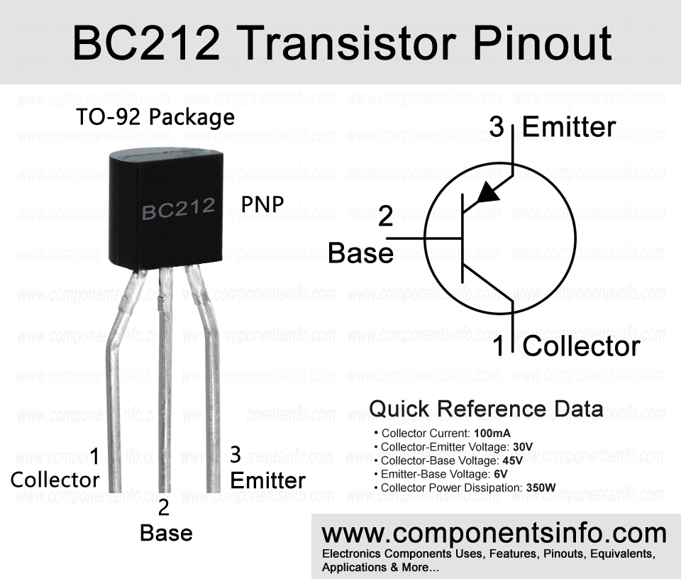
BC212 is another interesting PNP transistor available in TO-92 package. This post contains all the important information about this device such as BC212 transistor pinout, uses, features, applications and other useful data.
Absolute Maximum Ratings:
- Package Type: TO-92
- Transistor Type: PNP
- Max Collector Current(IC): –100mA
- Max Collector-Emitter Voltage (VCE): –50V
- Max Collector-Base Voltage (VCB): –60V
- Max Emitter-Base Voltage (VEBO): –5V
- Total Device Dissipation (Pc): 350 miliWatt
- Max Transition Frequency (fT): 200 MHz
- Minimum & Maximum DC Current Gain (hFE): 60 to 400
- Max Storage & Operating temperature Should Be: -55 to +150 Centigrade
Replacement and Equivalent:
BC560, BC557, BC559, BC558, BC556, A733
BC212 Transistor Explained / Description:
BC212 is an interesting PNP transistor available in TO-92 package. It is a transistor of BC21x series which also contains other transistors which are BC213 and BC214. These two transistors are almost same as BC212 so you can use them alternatively in most of the applications, the only main difference is their collector-emitter voltage which is about -30V in BC213 and BC214 but if your application is operating under 24V then you can easily replace them.
The features of this transistor make it very interesting and effective. Some of its features are low noise and high gain capability, transition frequency of up to 200MHz, DC current gain of 60 to 400, and collector-emitter voltage of up to -50V. All these features make BC212 an ideal transistor to be used in a wide variety of applications.
Now looking at the absolute maximum ratings of the transistor the collector-emitter voltage is -50V, continuous collector current is 100mA, collector-base voltage is -60V, emitter-base voltage is -5V, total device dissipation is 350mW and operating and storage junction temperature is from -55°C to +150°C.
How to Use This Transistor:
It is a BJT transistor so the using procedure is same as we use in any other PNP BJT transistor by connecting its emitter to the positive rail of the circuit, its base to the signal from which you want to control the load (for switching circuit) or the signal you want to amplify (for amplifier circuit) and connect the load with the collector in switch circuit or getting the amplified output from collector in amplifier circuit. This is just a simple concept to understand how to use the transistor as a switch or amplifier but to make these circuits properly you should have to use some passive components. You can easily found one transistor switch or amplifier circuit by searching online.
Applications:
Audio Preamplifier Circuits
Audio Amplifier Circuits
Solar Circuits
Audio Amplifier Stages
Battery Charger Circuits
Darlington Pairs
Low Level Signal Amplification
Switching Circuits
Automotive Circuits
Tx and Rx Circuits
Safe Operating Guidelines:
Here are some guidelines for the safe operation of the transistor.
- To safely operate the transistor always use the transistor at least 20% below from its absolute maximum ratings.
- The max collector-emitter voltage is -50V but by cutting 20% from the total value we will get -40V so we will not drive load of more than -40V.
- The max continuous collector current is 100mA but again according to the above 20% rule we will only use 80mA.
- Before placing the transistor in the circuit always check its pin layout.
- The storage and operating temperature should be between: -55°C to 150°C.
Datasheet:
To download the datasheet just copy and paste the below link in your browser.
https://www.alldatasheet.com/datasheet-pdf/view/2880/MOTOROLA/BC212.html


