Understanding BC213 Transistor Pinout, Applications, Equivalents, Features and Other Details
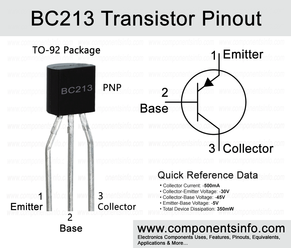
BC213 is another PNP transistor of BC21X series of general purpose transistors. Today we are going to understand BC213 transistor pinout, applications, equivalents, features and other details.
Absolute Maximum Ratings:
- Package Type: TO-92
- Transistor Type: PNP
- Max Collector Current(IC): –500mA
- Max Collector-Emitter Voltage (VCE): –30V
- Max Collector-Base Voltage (VCB): –45V
- Max Emitter-Base Voltage (VEBO): –5V
- Total Device Dissipation (Pc): 350 miliWatt
- Max Transition Frequency (fT): 360 MHz
- Minimum & Maximum DC Current Gain (hFE): 80 to 400
- Max Storage & Operating temperature Should Be: -55 to +150 Centigrade
Replacement and Equivalent:
BC526B, BC214B, 2SA1625, 2SA1391, 2SA1318, BC214C, 2SA1392, BC526C, 2SB1059
BC213 Transistor Explained / Description:
BC213 is a PNP transistor of BC21X series which also contains other transistors such as BC212 and BC214. All the transistors of this series are designed to be used in general purpose applications. The transistor possesses some very good features which are collector current of -500mA, maximum noise figure of 10dB, upto 360MHz transition frequency and total device dissipation of 350mW.
The absolute maximum ratings of the transistor are collector-emitter voltage is -30V, continuous collector current is -500mA, collector-base voltage is -45V, emitter-base voltage is -5V, total device dissipation is 350mW and max operating and storage temperature is -55°C to +150.
According to the above characteristics and features this transistor can be used in wide variety of general purpose applications such as switching, amplification, RF applications, low noise and high gain applications.
How to Use the Transistor:
To use the transistor as a switch connect its emitter with the positive rail of the circuit, apply signal (signal from which you want to control the output) at the base pin through a suitable current limiting resistor (most of the time 1K resistor is used), and connect the load between the collector and the negative rail of the circuit.
To use the transistor as a simple amplifier provide signals that you want to amplify at the base pin through a capacitor. A capacitor is used here to block any DC in the signals and because the audio signals are in AC form therefore the purpose is to only provide AC signals to the transistor. Next connect the emitter with the positive rail of the circuit and the collector pin is connected with the output device through a capacitor. The output device can be a capacitor or the next stage of amplification. This is a guide to use the transistor as a simple amplifier but to enhance output audio you have to use some passive components.
Applications:
Switching Circuits
Automotive Circuits
Darlington Pairs
Audio Amplifier Circuits
Audio Preamplifier Circuits
Tx and Rx Circuits
Audio Amplifier Stages
Battery Charger Circuits
Solar Circuits
Signal Amplification
Safe Operating Guidelines:
To safely operate the transistor do not use it to its absolute maximum ratings and always use it at least 20% below from these ratings. So according to the above 20% below usage guide the maximum collector-emitter voltage of the transistor is -30V but we will not drive load of more than 24V. The maximum continuous collector current is -500mA so we will only use 400mA. The maximum storage and operating temperature should be between -55°C to 150°C.
Datasheet:
To download the datasheet just copy and paste the below link in your browser.
https://www.alldatasheet.com/datasheet-pdf/view/2882/MOTOROLA/BC213.html


