BD535 Transistor Pinout, Uses, Features, Equivalents, Safe Operating Guidelines and Other Details
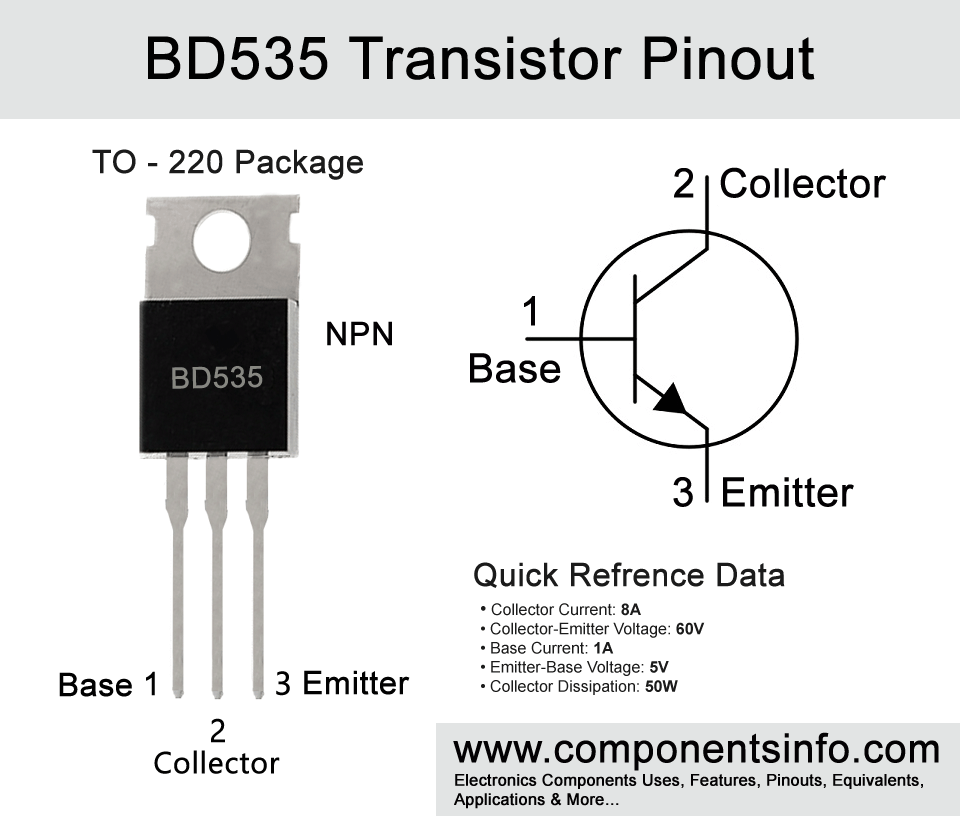
BD535 is an NPN available in TO-220 package. In this post we are going to discuss BD535 transistor pinout, uses, features, equivalents, safe operating guidelines and other details.
Absolute Maximum Ratings:
- Package Type: TO-220
- Transistor Type: NPN
- Max Collector Current(IC): 8A
- Max Collector-Emitter Voltage (VCEO): 60V
- Max Emitter-Base Voltage (VEBO): 5V
- Max Base Current (IB): 1A
- Max Collector Power Dissipation (Pc): 50W
- Minimum & Maximum DC Current Gain (hFE): 15 to 150
- Max Storage & Operating temperature Should Be: –65 to +150 Centigrade
PNP Complementary:
PNP Complementary of BD535 is BD536
Replacement and Equivalent:
BDX43, BDX41, BDX53/A/B/C, BDX33/A/B/C, BDW93/AB/C, TIP132, TIP131, TIP130, TIP101, BD899, BD897, BD649, BD645, BD543, BD537, 2SD1827, 2SD1277, 2SD1192, 2SC4551, 2SC3710, 2SC3346, 2SC3255, 2N6045, 2N6531, 2N6388, 2N6387.
BD535 Transistor Explained / Description:
BD535 is an NPN power transistor designed to be used in switching and medium power liner applications. It has many features and also some benefits such as low saturation voltage, drive load of upto 8A, drive upto 60V loads, transition frequency of 3MHz to 12MHz etc.
BD535 is a transistor of BD53X series and there are also other transistors in the series which are BD533 and BD537. There are also complimentary series of these transistors which are BD534 (complimentary of BD533), BD536 (complimentary of BD535), and BD538 (complimentary of BD537).
The pin layout of the BD535 and its series are as follows:
When looking from the part number side of the transistor, the first pin (starts from the left) is Base, Second pin (middle pin) is Collector and the third pin (at the right side) is Emitter.
Now looking at the absolute maximum ratings of the transistor, the collector-emitter voltage of the transistor is 60V, collector-base voltage is 60V, emitter-base voltage is 5V, base current is 1A, collector current is 8A, junction temperature is 150°C and storage temperature is from -65°C to 150°C.
Where We Can Use it & How to Use:
BD535 is designed to use in switching and medium power linear applications the good absolute maximum ratings and electrical characteristics makes it suitable for wide variety of applications such as amplifiers, power supplies, controller circuits, switching regulators etc.
For using the transistor as a switch apply signal to its base through a suitable current limiting resistor. Connect the load between the collector and positive rail of the circuit and its emitter pin with the ground.
For using transistor as a simple amplifier apply the signal which you want to amplify to its base through a suitable capacitor and a biasing network of two resistors. The collector should be connected to the positive rail of the circuit through a load resistor and the emitter should be connected with the ground through a resistor and a capacitor connected in parallel. The amplified signal should be collected from the collector of the transistor.
Applications:
Motor Driver Circuits
Audio Amplifiers
Lighting Control Circuits
Power Supplies
DC-DC Converters
Battery Charger Circuits
Voltage regulators
Safe Operating Guidelines:
Here are the safe operating guidelines of the transistor.
- It is suggested to always use the transistor 20% below from its absolute maximum ratings.
- So therefore the maximum collector is 8A but we will not drive load of more than 6.4A.
- The maximum collector-emitter voltage of the transistor is 60V therefore we will not drive load of more than 48V.
- A suitable heatsink will be required with the transistor.
- Always store or operate the transistor at temperatures above -65°C and below 150°C.
Datasheet:
To download the datasheet just copy and paste the below link in your browser.
https://eu.mouser.com/datasheet/2/389/stmicroelectronics_cd00000915-1204519.pdf


