BD675 Transistor Pinout, Features, Equivalent, Applications and Other Details
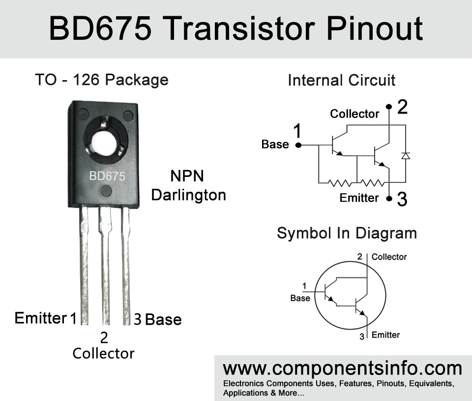
BD675 is a NPN Darlington transistor available in TO-126 transistor package. It is a transistor of BD6XX series. Today we are going discuss BD675 transistor pinout, features, equivalent, applications and other details about this device.
Absolute Maximum Ratings:
- Package Type: TO-126
- Transistor Type: NPN Darlington
- Max Collector Current(IC): 4A
- Max Collector-Emitter Voltage (VCEO): 45V
- Max Collector-Base Voltage (VCBO): 45V
- Max Emitter-Base Voltage (VEBO): 5V
- Max Collector Power Dissipation (Pc): 40 Watt
- Minimum DC Current Gain (hFE): 750
- Max Storage & Operating temperature: -55 to +150 Centigrade
PNP Complementary:
PNP Complementary of BD675 is BD676
Replacement and Equivalent:
BD675A, BD677, BD677A, BD679, BD679A, BD681, MJE801, MJE800, MJE803, MJE802, BD779, BD775, BD679, BD677.
BD675 Transistor Explained / Description:
BD675 is a high gain Darlington transistor available in TO-126 package. It is a transistor of BD6XX series which also contains other transistors such as BD675A, BD677/A, BD679/A, and BD681, all the transistors in this series are almost the same the only difference is their voltage ratings so if you want to replace any transistor in the series with another transistor of the series then you must check its collector-emitter voltage so if these ratings are higher then the transistor you are using then you can easily replace them.
BD675 absolute maximum ratings are as follows:
The collector current of the transistor 4A, collector-emitter voltage is 45V, emitter-base voltage is 5V, collector-base voltage is also 45V and collector power dissipation is 40 Watt.
The transistor is designed to be used in general purpose amplification applications but can also be used in a variety of other applications.
Where We Can Use it & How to Use:
The transistor can be used in many applications such as amplifier circuits, pulse circuits, controller circuits, driver circuits etc.
The using procedure of the transistor is not very difficult. First of all, decide what type of circuit you want to make with this transistor whether it is a switching circuit or an amplifier circuit. For using it as a switch first of all check its pin configuration and also check your load amperes and the voltage it requires because if the transistor has lower ratings as compared to the ampere and voltage of the load then the transistor will not work properly and can also get burned. After checking the ampere and voltage ratings connect the Base pin of the transistor with the signal source (through a resistor between 1K to 10K) from which you want to control the load. Connect the Emitter pin with the negative supply of the circuit and connect the Collector pin with the negative wire of the load and the positive wire of the load will be connected to the ground.
Now for using it as an amplifier, it is important to understand that there are different types of amplifier circuits which you can make but in this example, we are sharing a simple amplifier circuit. To make the simple amplifier circuit connect the Emitter pin with the ground, connect the Base pin with the signal source you want to amplify through a 102 ceramic capacitor, and connect the collector pin with the negative wire of the speaker and the positive wire of the speaker will be connected with the positive supply.
Applications:
Audio Amplifiers
Voltage inverters
Motor Control
Pulse Generator
Voltage Regulation
Switching Circuits
Battery Operated Applications
LED Drivers
DC to DC Converters
Safe Operating Guidelines:
Following are the guidelines to safely operate the transistor.
- Do not drive the transistor to its absolute maximum ratings and always stay at least 20% below from these ratings.
- So the maximum collector current is 4A therefore do not drive load of more than 3.6A.
- The maximum collector-emitter voltage is 45V, therefore do not drive load of more than 36A.
- Always store or operate the transistor at temperatures above -55°C and below 150°C.
Datasheet:
To download the datasheet just copy and paste the below link in your browser.
https://www.onsemi.com/pdf/datasheet/bd675-d.pdf


