KSP13 Transistor Pinout, Applications, Features, Equivalent and Other Useful Details
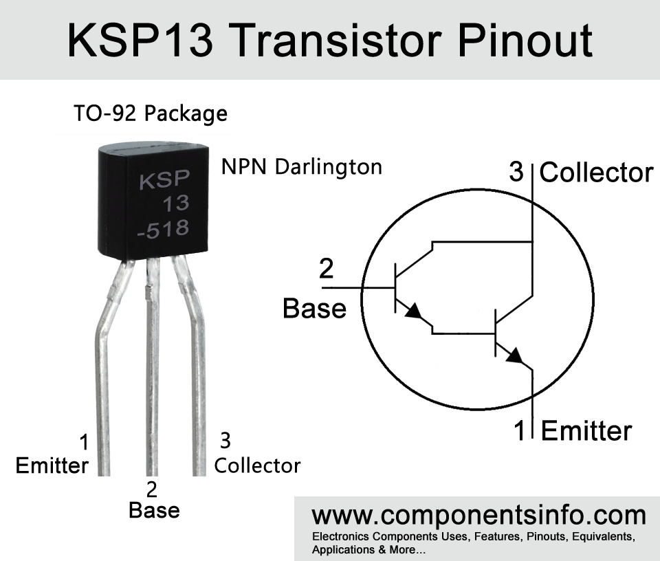
If you are looking for a general purpose TO-92 package darlington transistor with good electrical characteristics and max ratings then KSP13 might be a good choice. This article contains information about KSP13 transistor pinout, applications, features, equivalent and other useful details.
Features / Technical Specifications
- Package Type: TO-92
- Transistor Type: NPN
- Max Collector Current (IC): 500mA
- Max Collector-Emitter Voltage (VCEO): 30V
- Max Collector-Base Voltage (VCBO): 30V
- Max Emitter-Base Voltage (VEBO): 10V
- Collector Power Dissipation (PC): 625 mW
- DC Current Gain (hFE): 5000 to 10,000
- Max Storage & Operating Temperature Range: -55 to 150 °C
- Junction temperature: 150 °C
Replacement and Equivalent
MPSW45, MPSW13, MPSA13G, MPSA14, KSP26, KSP14, BC617, BC517G, 2SD2068, 2SD1931, 2SD1786, 2SD1698.
D1555 Transistor Explained / Description
Are you looking for a good general purpose darlington transistor in TO-92 package? If yes then KSP13 can be a good choice. A darlington transistor is a type of transistor that contains two transistors inside. These two transistors are connected in a way (you can also check the internal diagram in the pinout image above) which increases the gain to very high level. Due to the very high gain feature of darlington transistors these transistors perform very well in applications which require high gain signal amplification or where weak signal amplification is required such as in communication circuits, sensor circuits, audio and other signal amplification circuits. Moreover, this high current gain capability of these transistors also makes them ideal to use in motor control applications, controlling LEDs, relays and in many other applications.
Looking at the absolute maximum ratings of the transistor the collector-emitter voltage is 30V, collector-base voltage is 30V, collector current is 500mA, emitter-base voltage is 10V, collector power dissipation is 625mW, storage temperature is from -55 °C to 150°C and junction temperature is 150°C.
The electrical characteristics of the transistor are also good as a general-purpose transistor some of its electrical characteristics are DC current gain of 5000 to 10000, transition frequency is 125MHz, and collector-emitter saturation voltage is 1.5V.
Where We Can Use it & How to Use
KSP13 transistor can be used for a wide variety of purposes some of the categories are switching, controller and driver circuits, amplification, sensor circuits, etc.
To use the transistor first of all know the pin configuration of the transistor. The base pin of the transistor will be connected to the input signal that you want to amplify or use to trigger the output of the transistor and a suitable transistor should be used between base of the transistor and the signal source. The resistor should be selected according to the required current output or you can also connect a 5K or 10K variable resistor in series with a fixed 1K resistor to test how much minimum current the transistor is required to drive the output load. Now connect the load between the collector and the positive supply of the circuit and connect the emitter to the ground of the circuit.
Applications
Switching circuits to switch load such as relays, solenoids, LEDs etc.
Audio preamplifier circuits
Audio amplifier circuits
Motor control circuits
RF circuits around 125MHz
And variety of other applications
Safe Operating Guidelines
For long life and effective performance, it is important to follow the safe operating guidelines for the transistor.
- Do not operate the transistor to its absolute maximum ratings and stay at least 20% below from these ratings.
- Do not connect base directly with the signal source.
- Operate the transistor in temperature limits shown in the datasheet which is -55 °C to 150°C.
- Protect emitter-base junction of the transistor with reverse polarity or use a diode.
Datasheet
To Download the datasheet just copy and paste the below link in your browser.
https://z3d9b7u8.stackpathcdn.com/pdf-down/K/S/P/KSP13_FairchildSemiconductor.pdf


