LM339 Pinout, Equivalent, Applications, Features and Other Info
LM339 is a widely used IC, in this post we are going to discuss LM339 pinout, equivalent, applications, features, and other details about this IC.
LM339 IC Features / Technical Specifications
- Low current consumption, each comparator drains only 0.8mA
- All four comparators can be operated from a single supply.
- Operated from wide supply voltage from 2V to 36V.
- Operated from single and dual supply.
- Output compatibility with TTL and CMOS.
- Required only typically 25nA bias current.
- Available in multiple packages
- Low cost IC
- Reliable to use in commercial equipment and devices.
- Requires low voltage for saturation.
- Time duration of output short circuit to GND is unlimited.
LM339 IC Pin Configuration
| Pin# | Pin Name | Pin Description |
|---|---|---|
| 1 | Output 1 | The output of IC's First Comparator Opamp |
| 2 | Output 2 | The output of IC's Second Comparator Opamp |
| 3 | Vcc / Positive Supply | Positive Supply of IC / Positive Supply of All Comparator Opamps. |
| 4 | Input1(-) / Inverting Input 1 | Inverting Input of IC's First Comparator Opamp |
| 5 | Input1(+) / Non Inverting Input 1 | Non Inverting Input of IC's First Comparator Opamp |
| 6 | Input2(-) / Inverting Input 2 | Inverting Input of IC's Second Comparator Opamp |
| 7 | Input2(+) / Non Inverting Input 2 | Non Inverting Input of IC's Second Comparator Opamp |
| 8 | Input1(-) / Inverting Input 3 | Inverting Input of IC's Third Comparator Opamp |
| 9 | Input1(+) / Non Inverting Input 3 | Non Inverting Input of IC's Third Comparator Opamp |
| 10 | Input1(-) / Inverting Input 4 | Inverting Input of IC's Forth Comparator Opamp |
| 11 | Input1(+) / Non Inverting Input 4 | Non Inverting Input of IC's Fotrh Comparator Opamp |
| 12 | Ground (Gnd) | Ground / Negative Supply of IC / Negative Supply of All Comparator Opamp. |
| 13 | Output 4 | The output of IC's Forth Comparator Opamp |
| 14 | Output 3 | The output of IC's Third Comparator Opamp |
LM339 Description
LM339 is a 16 pin IC available in dip and other packages. The IC contains four independent comparators opamps which can be used for four different tasks at the same time and all the comparators can be powered with a same supply pins of the IC which are pin3 (Positive) and pin12 (Ground or Negative). The minimum and maximum supply voltage of the IC is 2V to 36V and the max output current of the IC is 20mA which means that the IC can drive a load of upto 20mA directly from its output pins but if a user want to drive a high current load than a transistor should be used accordingly.
The IC has low current requirements and can work easily on a single power supply which makes it ideal to use in portable and battery operated equipment and devices. Moreover it can also work with dual power supplies.
As said above the IC consists of four independent comparator opamps. As the name suggests “comparator” means it compares between two input voltages one is inverting input and another is non-inverting input, therefore if voltage at inverting input is higher than the non-inverting input then the output goes high and if the inverting input voltage is lower than the non-inverting input then the output goes low. Suppose we have connected a 10mA buzzer with the output of a comparator now when voltage at inverting input is higher than the non-inverting input the buzzer will beep and when the voltage at inverting input is lower than the non-inverting input the buzzer will off.
Applications
Comparator Circuits
Voltage Controlled Oscillator Circuits
Multivibrator Circuits
Timer Circuits
Measuring Circuits
Automotive Circuits
Replacement and Equivalent / Other Part Numbers
LM2901, LM3302, LM139, LM397, LM239, LM324, MC3302, NCV2901, MC3302, CA139, CA139A, CA239, CA339.
Application Circuit
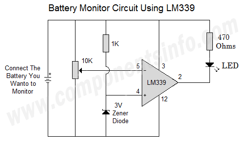
The circuit below shows a battery monitor circuit using LM339 IC. In this circuit we have only used one comparator of the IC that is comparator 1, but the other 3 comparators can be used with the same procedure to even get a more depth monitoring of a battery voltage. This circuit will compare the battery voltage from the preset level voltage set by the 10K variable resistor and when the battery voltage will reach to that preset level LED will become Off to indicate that the battery is below the preset level.
How to Safely Long Run in a Circuit
For long term performance of the IC it is recommended do not use IC on its max ratings and always use it 20% below its max ratings. The maximum output current of the IC is 20mA therefore do not drive load of more than 16mA. The max operating voltage is 36V therefore do not operate the IC from more than 28V. Prevent the IC from output short circuit to Vcc this may result in heating the IC and burn/damage the internal circuitry. Inputs must be under -0.3V. When operating the IC the temperature around the IC should be under +150 degrees centigrade and the storage temperature of the IC should be between -65 to +150 degrees centigrade.
Datasheet
To download the datasheet just copy and paste the below link in your browser.
https://cdn.datasheetspdf.com/pdf-down/L/M/3/LM339-STMicroelectronics.pdf


