LM393 Pinout, Datasheet, Features, Applications, Equivalent
LM393 is a widely used IC in automotive, industrial and educational applications. In this post you will find LM393 pinout, datasheet, features, applications, equivalent and other useful information about this chip.
LM393 IC Features / Technical Specifications
- Two separate voltage comparator operational amplifiers in a single package.
- Can be operated from single and dual power supplies.
- Operated from wide supply voltage from 2V to 36V.
- Requires low operating current around 400uA only.
- Requires very low input bias and offset current.
- It output can be easily used to drive most logic systems.
- High Accuracy
- Reliable to use in commercial devices.
- Low cost
- Suitable for portable / battery operated devices.
LM393 IC Pin Configuration
| Pin# | Pin Name | Pin Description |
|---|---|---|
| 1 | Output A | Output of IC's First Operational Amplifier |
| 2 | Inverting Input A | Inverting Input of IC's First Operational Amplifier |
| 3 | Non Inverting Input A | Non Inverting Input of IC's First Operational Amplifier |
| 4 | Ground (Gnd) | Ground / Negative For Both Op-amps of the IC. |
| 5 | Inverting Input B | Inverting Input of IC's Second Operational Amplifier |
| 6 | Non Inverting Input B | Non Inverting Input of IC's Second Operational Amplifier |
| 7 | Output B | Output of IC's Second Operational Amplifier |
| 8 | Vcc | Positive Supply of Op-amps of the IC. |
LM393 Description
LM393 is a widely used voltage comparator IC available in 8 Pin Dip, SO-8 and other packages. This small IC is packed with many good features that make it ideal IC to use as a comparator. The IC contains two separate high accuracy comparator opamps that can be operated from single or dual power supply. One good feature is its wide supply voltage range that makes it possible to use this IC in wide variety of applications. The IC also requires low operating current due to which it is ideal to use in portable and battery operated devices. The output drive logic systems therefore it can be used in digital circuits. On the other hand this IC is also widely used by electronic students, hobbyists and tinkerers in their project. The maximum output current of the IC is 20mA which his enough to drive transistors and logic systems, logic devices and microcontrollers.
Applications
Comparator Circuits
Voltage Detection
Oscillator Applications
Logic Systems Applications
Replacement and Equivalent / Other Part Numbers
LM193, LM293, LM2903, LM311, LM358
Application Circuit
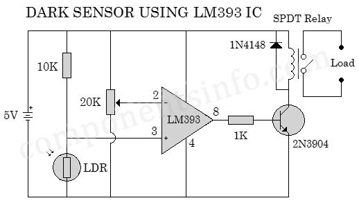
The schematic below is a dark sensor switch circuit using LM393 IC, the LM393 IC is used here as a comparator. The circuit is using an LDR as a sensor for light and darkness. The LDR is a light dependent resistor who’s resistance changes when the amount of light changes on its surface. The 20K variable resistor used here to calibrate the circuit to swith ON the load on the desired amount of light. At the output of the circuit a SPDT relay is derived through a 2N3904 BJT transistor. You can connect any load / appliance in series with the points marked “Load” in the circuit. The operating voltage of the circuit is 5V but you can operate from any voltage from 2V to 36V DC. The relay switch should be used according to the operating voltage for example if you are operating the circuit with 5V then use a 5V to 6V relay of if you want to operate it with higher voltage then use relay switch according to that voltage. Relay switches are available in different voltages like 3V, 5V, 6V, 9V, 12V etc.
How to Safely Long Run in a Circuit
To get stable and long term performance with LM393 it is suggested to not operate the IC with more than 32V DC. Do not operate more than ±18 when operating with dual power supply. For stable performance always operate some volts below from the max operating voltage. To not operate load more than 20mA, always carefully attach the pins accidental short circuit can cause damage to the internal circuitry of the IC by causing over heating in the internal circuitry. Wrong soldering can also cause damage to the internal circuitry of the IC or make weak due to which it will not perform as expected or provide unstable performance, wrong soldering includes unclean solder joints, attachment of soldering iron more than 10 seconds with any lead while soldering or providing any lead more than 300 Centigrade for 10 seconds to any lead will also damage the IC internally. Do not operate the IC in temperature below 0 degree centigrade and above +70 degree centigrade and always store the IC in temperature above -65 degree centigrade and below +150 degree centigrade.
Datasheet
To Download the datasheet just copy and paste the below link in your browser.
https://www.st.com/resource/en/datasheet/lm193.pdf


