TIP105 Transistor Ppinout, Applications, Features, Equivalents and Other Useful Information
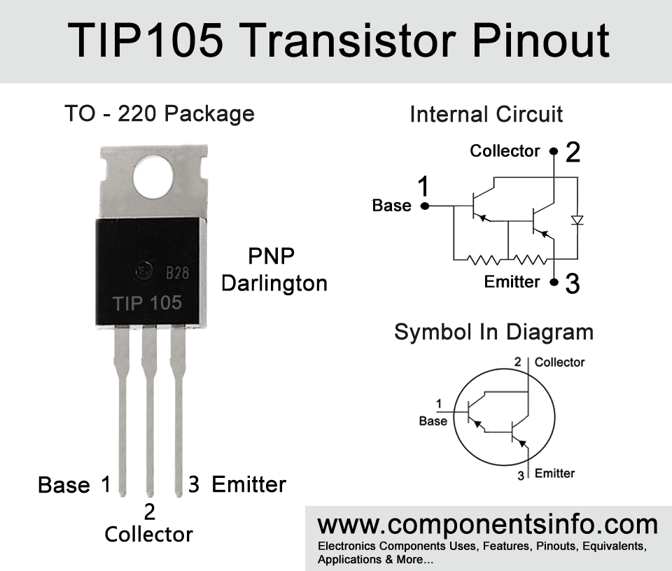
TIP105 is a PNP darlington transistor available in TO-220 package. The transistor is designed to use in general purpose type audio amplifiers and also for switching of low speed type. In this post we are going to discuss in detail about TIP105 transistor pinout, applications, features, equivalents and other useful information such as where and how to use it, safe operating guidelines etc.
Features / Technical Specifications:
- Package Type: TO-220
- Transistor Type: PNP Darlington
- Max Collector Current(IC): –8A
- Max Peak Collector Current(ICM): –15A
- Max Collector-Emitter Voltage (VCE): –60V
- Max Collector-Base Voltage (VCB): –60V
- Max Emitter-Base Voltage (VEBO): –5V
- Total Power Dissipation (PD): 80 Watt
- Minimum & Maximum DC Current Gain (hFE): 1000 To 20000
- Max Storage & Operating temperature: -65 to +150 Centigrade
NPN Complementary:
NPN Complementary of TIP105 is TIP100
Replacement and Equivalent:
TIP106, TIP107, NTE2344, BDT64, BD646, BD546A/B/C, BD538, BD304, 2N6667, 2N6667, BD898, BD808, BD800, BD652, BD646.
TIP105 Transistor Explained / Description:
TIP105 is a PNP darlington transistor designed to use in amplifiers, low speed switching & variety of general purpose applications. The transistor is manufactured in TO-220 package and the pin configuration of the transistor are the first pin is Base, second is Collector and the third pin is Emitter.
The transistor has many good features which are:
Low Collector-Emitter Saturation Voltage
The low collector-emitter saturation voltage helps decrease power loss during the transistor’s operation or when the transistor is in saturation or in other words we can say it when it is fully ON.
High DC Current Gain
The high DC current gain means that the transistor is capable to amplify electrical signals fed to its base to a very high level.
Monolithic Construction with Built-in Base-Emitter
This means that the transistor is totally made as one piece and also contains some components inside which helps it work better.
Collector-Emitter Sustaining Voltage
Collector emitter sustain voltage is a voltage level on which the transistor can work stable without getting damage.
Looking at the absolute maximum ratings of the transistor the collector-base voltage is -60V, collector-emitter voltage is also -60V, the collector current is -8A, peak collector current is -15A, emitter-base voltage is -5V, the base current is -1A and collector power dissipation is 80W. These are the max ratings or max limits of the transistor but it doesn’t mean that we can always use the transistor on these ratings. The absolute maximum ratings mean that these are the maximum limits of the transistor on which this transistor can handle for a very small or short period of time. So it doesn’t mean that we can always use the transistor on these ratings. Continuously using the transistor on its max ratings can damage the transistor or weaken its performance.
Where We Can Use it & How to Use:
TIP105 is designed to be used for amplification, low speed switching and variety of general purpose applications. The transistor can be used in variety of switching, amplification and other circuits such as power control, voltage regulation, sensor circuits, instrument circuits, etc.
Applications:
Driving or switching loads upto -8A
Inverter Circuits
Robotics
Audio amplifier circuits
Low speed switching
Home Automation
Security Devices
Motor driver circuits
Relay Drivers
Battery charger circuits
Instrument Circuits
Portable and battery operated applications
Industrial Applications
How to Safely Long Run in a Circuit:
These safe operating guidelines are a must to follow when using the transistor.
- Do not exceed collector current and peak collector current.
- Always check the total power dissipation and make sure that it is under the max limits.
- Use diodes to prevent the transistor from voltage spikes.
- The transistor should be operated or stored between its max temperature limits.
- A heatsink should be used with the transistor.
- Stay at least 20% below its maximum ratings.
.
Datasheet:
To download the datasheet just copy and paste the below link in your browser.
https://z3d9b7u8.stackpathcdn.com/pdf-down/T/I/P/TIP105_FairchildSemiconductor.pdf


